ZTL TECH is now Zintilon. We’ve updated our name and logo for a fresh start. Check Now
Metal Core PCB Manufacturing
We build circuit layers on aluminum, copper, or ceramic cores (1–170 W/m·K) with high-thermal-conductivity dielectrics to create “PCB-level heat sinks” that remove heat 5–9× faster than FR-4.Multiple substrate choices.
- Maximum panel size 54 inches
- Maximum panel thickness 0.450 inches
Start a new PCB Quote
Please compress all .gbr files before uploading
All uploads are secure and confidential
Our Metal Core PCB Capabilities
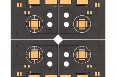
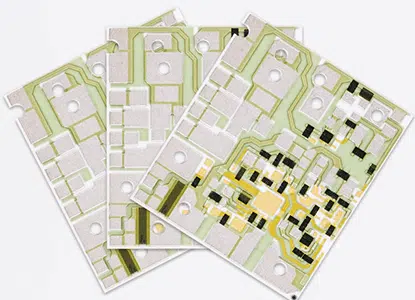
Zintilon offers end-to-end metal-core fabrication—from 0.5 mm Al LED strips to 3 mm Cu power modules. We handle special dielectrics, plated through-holes, selective hard-gold, and vacuum reflow, delivering consistent thermal performance and electrical reliability.
Metal Core PCB Materials
| Layer | Typical Options | Key Performance | Thickness | Application Notes |
| Circuit Copper | ED/RA foil, 35–140 µm | 58 MS/m, plateable to 4 oz | 35–140 µm | High-power pads can be locally plated thicker |
| Thermal Dielectric | ① Epoxy + ceramic filler (1–3 W/m·K) | Electrically isolating, CTE matched | 50–200 µm | LED 1–2 W/m·K OK; >100 W supplies choose ≥5 W/m·K |
| ② Polyimide + BN (3–8 W/m·K) | Flexible, 300 °C solderable | 50–125 µm | Bendable heat-spreader | |
| ③ Nano-ceramic coat (>8 W/m·K, 6 kV breakdown) | Ultra-thin, high voltage | 25–75 µm | mmWave or high-voltage drivers | |
| Metal Core | ① Al 5052/6061 (205 W/m·K) | Light, cheap, extrudable | 0.5–3 mm | Cost-performance leader |
| ② Cu C1100 (385 W/m·K) | Best λ, heavy | 0.5–3 mm | EV power modules, lasers | |
| ③ Stainless 430 (16 W/m·K) | Corrosion-proof | 0.5–2 mm | Sensors, marine, chemical |
Metal Core PCB Surface Finishes
| Finish | Thickness | Features | Metal-Core Fit | Typical Apps | Notes |
| HAL-LF SnCu | 1–2 µm | Low cost, reworkable | Al needs thin Ni barrier | Consumer LED strips | 270 °C dip, pre-heat thick Al |
| ENIG | Ni 3–5 µm + Au 0.05 µm | Flat, bondable, 12 mo shelf | Process ≤80 °C to limit Al oxide | Auto LED, COB | Must micro-etch Al first |
| ENEPIG | +Pd 0.05 µm | Sn & Al/Au wire, highest reliability | +20 % cost, high-rel | Laser modules | Best joint integrity |
| Immersion Ag | 0.15–0.3 µm | Low loss, flat | ≤6 oz Cu, vacuum pack | RF + power mixed board | 6 mo shelf, anti-tarnish |
| OSP | 0.2 µm | Cheapest, single-reflow | Al needs thin Cu strike | Low-power bulbs | Not for multiple reflow |
| Anodizing (Al base) | 5–15 µm Al₂O₃ | Insulating, 500 V, ε≈0.9 | Non-solder areas only | Integrated heat-sink | Adds 3–5 °C by radiation |
Why Choose Our
Metal Core PCB Services?

One-on-One Quotation
Upload your Gerber files and get a quote within 24 hours. Our engineers review your design to avoid misunderstandings and offer competitive pricing.

High-Quality Production
We strictly control materials, processes, surface finishes, AOI, and flying probe tests to ensure consistent quality from prototype to mass production.

Fast Delivery
With advanced equipment and a professional team, we prioritize your order based on complexity and urgency.

Instant Communication
We provide full technical support from quote to delivery. We respond quickly to any questions until you receive your PCBs and are fully satisfied.
Metal Core PCB Standards
We follow the tolerance standards of ISO 2768 (medium grade, fine grade) and ISO 286 (grade 8, 7, 6). You are welcome to emphasize it in the drawings or communicate with the sales for higher precision needs. We follow ISO2768m by default in the absence of special requirements.
Item
Sub Item
Parameter
Thermal Performance
Design Key Thermal conductivity, dielectric layer
Empirical Value / Formula 1–8 W/m·K (LED 1–2 W/m·K; >100 W modules ≥5 W/m·K)
Design Key Board thermal resistance
Empirical Value / Formula ≤0.5 °C/W (3 mil ceramic ≈0.09 °C-in²/W)
Design Key Thermal via array
Empirical Value / Formula 0.3–0.5 mm dia, 1.0–1.5 mm pitch, 35–70 µm copper wall, filled with high-κ paste or copper
Design Key Base thickness
Empirical Value / Formula Al 0.5–3 mm (5052/6061); Cu 0.5–3 mm (C1100); thicker bases use step-drill or copper coin
Electrical & Material Standards
Design Key Breakdown voltage
Empirical Value / Formula ≥3 kV AC (general), ≥6 kV with nano-ceramic dielectric
Design Key Dk
Empirical Value / Formula 3.5–4.5 @ 1 MHz, tolerance ±0.2 (low-Dk ceramic for RF)
Design Key Copper foil
Empirical Value / Formula ED/RA 1–10 oz; local plate to 20 oz; Rz ≤3 µm to reduce under-cut
Design Key CTE match
Empirical Value / Formula Al 23 ppm/°C vs Cu 17 ppm/°C → symmetrical stack + low-flow adhesive, warpage ≤0.75 % diagonal
Design Key Peel strength
Empirical Value / Formula ≥1.5 N/mm after thermal stress
Mechanical & Manufacturing Rules
Design Key Min line/space
Empirical Value / Formula outer 0.1 mm (4 mil), inner 0.13 mm (5 mil); prohibit <0.2 mm traces in heavy-copper zones
Design Key Hole-to-copper ring
Empirical Value / Formula ≥0.4 mm anti-tear; metal-base holes plugged with insulating resin before plating
Metal Core PCB Guidelines
Ensure precise tolerances, select appropriate materials, maintain clear CAD designs, and follow toolpath optimization for best results. Zintilon delivers accuracy, quality, and consistency in every machined part.
Dimension
Design Key
Empirical Value / Formula
Source / Notes
Thermal budget
Design Key Target RθJA ≤10 K/W (natural)
Empirical Value / Formula RθJA = RθJC + RθTIM + RθHS
Source / Notes Icepak/Flotherm verify, LED Tj ≤110 °C
Dielectric thickness
Design Key As thin as insulation allows
Empirical Value / Formula 1 kV → 75 µm nano-ceramic OK
Source / Notes Halving thickness cuts Rθ by 40 %
Thermal via array
Design Key 0.3–0.5 mm dia, 1.0–1.5 mm pitch, 35–70 µm copper wall
Empirical Value / Formula Filled/plugged, λ↑30 %
Source / Notes Use copper-filled or high-κ plug
Copper traces
Design Key Power ≥2 oz, signal 1 oz, selective plate
Empirical Value / Formula ΔT ≤20 °C @ 4 A / 2 oz
Source / Notes Avoid full-board thick Cu to save etch cost
Base thickness
Design Key 0.8–1.5 mm LED; ≥2 mm power modules
Empirical Value / Formula Thicker spreads heat but adds weight/cost
Source / Notes Match contact area to heat-sink
Machining
Design Key Al: CNC/V-cut; Cu: laser cut
Empirical Value / Formula ±0.1 mm, burr <20 µm
Source / Notes Mill thick Cu first, then cut to avoid delam
Surface color
Design Key Black anodize, matte black ε≈0.9
Empirical Value / Formula Extra 3–5 °C drop in natural convection
Source / Notes Outdoor luminaires must-have
Manufacturability
Design Key Al pre-heat 120 °C, back-drill ≤8 k rpm
Empirical Value / Formula Prevents CTE mismatch tear
Source / Notes Max Al panel 600 × 1200 mm, discuss with fab early
Our Custom Metal Core PCB Services for Various Industrial Applications
Prototyping and production parts from Zintilon have been applied to the various walks of life. The brilliant custom CNC machining service simplifies the process of obtaining good-quality production parts.


Metal Core PCB FAQs
Our maximum CNC machining part size is 3000 mm x 2200 mm x 1100 mm.
Our CNC machining standard tolerances range from plus or minus 0.001mm.
The cost of CNC machining is determined by the material, machining costs, labor costs, and the tooling and surface finish involved. Feel free to contact us for a quick quote.
Got any more questions?
Ultimate Guide
to Metal Core PCB
to Metal Core PCB

Metal Core PCB Manufacturing
Various and Robust Metal Core PCB Services

Process 1
Prototyping
Zintilon's rapid prototype service bridges the gap between product concept and market during the product development. Advanced CNC machines such as Hermle 5 axis cnc milling centers, multiple international certifications, and top-notch CMM inspection ensure the accuracy and details of the prototype, meeting high standards of quality requirements.
- Advanced Technology: CNC, CMM inspection, elite engineers etc.
- Quick Response: full support to ensure problem solved.
- Customized service: customize precision machining solutions

Process 2
Production
Zintilon's on-demand production solution provides customers with a modern, efficient and customer-oriented production solution through its flexibility, high quality standards by our robust supply network and self-owned CNC shop, strict quality control inspection, etc.
- Reasonable planning: precision resource allocation to ensure quick cycle time.
- Machining SOP : advanced technology and strict QC processes.
- Flexible Production: from rapid prototyping (1-20pcs) to low-volume production (20-1000pcs).
Let’s Build Something Great, Together