ZTL TECH is now Zintilon. We’ve updated our name and logo for a fresh start. Check Now

COB PCB Assembly

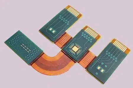
COB PCB Assembly refers to a "chip-level board-level packaging" technology where bare chips (Dies) are directly mounted on a PCB, with electrical connections achieved through gold wire/aluminum wire bonding, and encapsulated using epoxy resin or silicone.
  • Maximum panel size 54 inches
  • Maximum panel thickness 0.450 inches

Start a new PCB Quote

COB PCB Assembl parts prototypes

Please compress all .gbr files before uploading
All uploads are secure and confidential

Our COB PCB Assembly Service Capabilities

Zintilon Technology is committed to providing advanced COB PCB assembly services to global users, supporting COB PCB assembly from prototype production in the product R&D stage to small-batch manufacturing. From printing to assembly, we ensure to deliver efficient and reliable COB PCB assembly solutions for you.
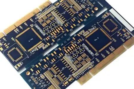
COB on FR4 PCB Assembly

COB-on-FR4 PCB Assembly

COB MCPCB PCB Assembly

COB-MCPCB PCB Assembly

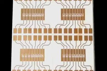
COB Ceramic PCB Assembly

COB-Ceramic PCB Assembly

COB PCB Assembly Materials

CategoryRecommended Model/SpecificationKey ParametersRemarks
Bare Die Bonding① Conductive Silver Adhesive (EP3-EP17); ② Insulating Epoxy Adhesive (EP138)Curing condition: 120–150°C for 30 minutes; Thermal conductivity: 2–5 W/m·K; Shear strength: ≥ 15 MPaSilver adhesive is used for power chips, while insulating adhesive is used for signal chips
Bonding Wire① Gold Wire (25 µm, Au 99.99%); ② Aluminum Wire (30 µm, Al 99%)Tensile strength: ≥ 6 g for gold wire, ≥ 4 g for aluminum wire; Arc height: 0.10–0.25 mmGold wire is used for high-reliability applications, and aluminum wire for cost-sensitive scenarios
Substrate PCB① High Tg FR-4 (Shengyi SY-1140); ② Metal Core PCB (MCPCB, 6061 Aluminum)Tg ≥ 170°C; CTE: 13–15 ppm; MCPCB thermal conductivity: 1–3 W/m·KAluminum substrates are preferred for LED COB, and FR-4 for signal COB
Encapsulation Adhesive① High-Transmittance Silicone (OE-6650); ② Low-Stress Epoxy (EP-121)Light transmittance: ≥ 90%; Hardness: 60–95 Shore D; CTE: 26 ppmOutdoor applications require UV resistance (no yellowing after 1000 hours of UV exposure)
Thermal Interface Material (TIM)Silicone Pad or Thermal Grease (2–5 W/m·K)Thickness: 0.1–0.2 mm; Dielectric strength: ≥ 3 kVUsed between the module and heat sink

COB PCB Assembly Surface Finishes

ProcessThicknessAdvantages in COBLimitations
ENEPIG (Electroless Nickel Electroless Palladium Immersion Gold)Ni 3–5 µm + Pd 0.05 µm + Au 0.03 µmCompatible with both gold wire and aluminum wire bonding; resistant to black nickel; wire bonding strength ≥ 6 gHighest cost
ENIG (Electroless Nickel Immersion Gold)Ni 3–5 µm + Au 0.05 µmSuitable for conventional gold wire bonding; flatness < 0.3 µmPlasma cleaning required for aluminum wire bonding
Immersion Silver (ImAg)0.15–0.3 µmIdeal for high-frequency signal COB; low skin effect lossRequires vacuum packaging; storage life: 6 months
OSP (Organic Solderability Preservative)0.2 µmUltra-low RF loss; suitable for non-heating areas of LEDsNot resistant to multiple high-temperature cycles; limited to one-time encapsulation

Why Choose Our
COB PCB Assembly Service?

1 2

One-on-One Quotation

Simply upload your .gbr file to receive a quotation feedback within 24 hours. Our professional engineers will analyze your design to avoid misunderstandings, communicate with you, and provide a reasonable price.

1 3

High-Quality Assembled

We maintain a rigorous and responsible attitude toward materials, processes, surface treatments, A.O.I (Automated Optical Inspection), and flying probe testing, ensuring consistent high quality from prototype production to mass manufacturing.

1 1

Fast Delivery

Equipped with advanced machinery and a professional quotation team to ensure fast delivery. We prioritize orders based on requirements and complexity.

1 4

Real-Time Communication

For your benefit, we provide full-cycle technical support for each customer from quotation to delivery. We will respond quickly to any questions until you confirm satisfactory COB PCB assembly.

COB PCB Assembly Standards

We follow the tolerance standards of ISO 2768 (medium grade, fine grade) and ISO 286 (grade 8, 7, 6). You are welcome to emphasize it in the drawings or communicate with the sales for higher precision needs. We follow ISO2768m by default in the absence of special requirements.

Parameter

Wire-bond (glue)

Flip-chip (bump)

Note

Placement accuracy
Value/Requirement ±10 µm @ 3σ
Source/Remarks ±5 µm @ 3σ
Cpk ≥1.33
Adhesive/bump height
Value/Requirement 20–50 µm (Ag-epoxy)
Source/Remarks 50–80 µm bump
Voids <10 % area
Cure profile
Value/Requirement 120–150 °C / 30–60 min
Source/Remarks Vacuum 5 mbar / 10 s
Shear ≥15 MPa

COB PCB Assembly Guidelines

Ensure precise tolerances, select appropriate materials, maintain clear CAD designs, and follow toolpath optimization for best results. Zintilon delivers accuracy, quality, and consistency in every machined part.

Item

Value/Requirement

Source/Remarks

Chip Bonding Area Size
Value/Requirement Bare die periphery + 0.2–0.4 mm
Source/Remarks Ensures adhesive overflow and prevents air bubbles
Conductive Adhesive Layer Thickness
Value/Requirement 20–50 µm (for silver adhesive)
Source/Remarks Thermal conductivity: 2–5 W/m·K; air bubble area < 10%
Bonding Pad
Value/Requirement NSMD (Non-Solder-Mask-Defined) opening; copper pad ≥ 100 µm × 100 µm; pitch ≥ 75 µm
Source/Remarks Compatible with 25 µm gold wire
Bonding Wire Arc Height
Value/Requirement 0.10–0.25 mm (low loop)
Source/Remarks Encapsulation adhesive thickness ≥ 0.5 mm for full coverage
Encapsulation Adhesive Thickness
Value/Requirement 0.5–1.5 mm (depending on chip height)
Source/Remarks Hardness: 60–95 Shore D; CTE: 26 ppm
Curing Parameters
Value/Requirement Silicone: 150°C for 60 minutes; Epoxy: 120°C for 30 minutes
Source/Remarks Curing degree ≥ 95%; no volatile voids
Tensile Test
Value/Requirement Gold wire ≥ 6 g; Aluminum wire ≥ 4 g; Shear strength ≥ 15 MPa
Source/Remarks JEDEC JESD22-B116
Thermal Cycling
Value/Requirement -40 ↔ +125°C for 500 cycles; wire tensile strength reduction ≤ 20%
Source/Remarks IPC-A-610 G Class 3
UV Resistance
Value/Requirement Outdoor adhesive: 1000 hours @ 85°C/UV-A 340 nm; ΔYI < 3
Source/Remarks No yellowing; light transmittance retention ≥ 90%

Our COB PCB Assembly Service for Various Industrial Applications

Prototyping and production parts from Zintilon have been applied to the various walks of life. The brilliant custom CNC machining service simplifies the process of obtaining good-quality production parts.

COB PCB Assembly FAQs

Our maximum CNC machining part size is 3000 mm x 2200 mm x 1100 mm.

Our CNC machining standard tolerances range from plus or minus 0.001mm.

The cost of CNC machining is determined by the material, machining costs, labor costs, and the tooling and surface finish involved. Feel free to contact us for a quick quote.
Got any more questions?
Ultimate Guide 
to COB PCB Assembly

COB PCB Assembly Service

Various and Robust COB PCB Assembly Services
prototyping
Process 1

Prototyping

Zintilon's rapid prototype service bridges the gap between product concept and market during the product development. Advanced CNC machines such as Hermle 5 axis cnc milling centers, multiple international certifications, and top-notch CMM inspection ensure the accuracy and details of the prototype, meeting high standards of quality requirements.
  • Advanced Technology: CNC, CMM inspection, elite engineers etc.
  • Quick Response: full support to ensure problem solved.
  • Customized service: customize precision machining solutions
production
Process 2

Production

Zintilon's on-demand production solution provides customers with a modern, efficient and customer-oriented production solution through its flexibility, high quality standards by our robust supply network and self-owned CNC shop, strict quality control inspection, etc.
  • Reasonable planning: precision resource allocation to ensure quick cycle time.
  • Machining SOP : advanced technology and strict QC processes.
  • Flexible Production: from rapid prototyping (1-20pcs) to low-volume production (20-1000pcs).
COB PCB Assembly
Service at Zintilon


CNC Router vs CNC Mill: Which CNC Machining Service Should I Choose?

CNC Router: Mainly used for engraving, drilling and cutting various materials such as wood, plastic, metal and composite materials. Suitable for machining large plates and soft materials.

CNC Mill: Compared with CNC routers, CNC milling machines are more suitable for processing hard materials such as steel and titanium. They usually have a higher Z-axis movement range, suitable for machining large block materials, and have a more solid structure and higher precision. CNC milling machines use spiral end mills, while CNC routers can use straight-edge router tools, but straight-edge tools are not suitable for metal machining

Click CNC Router vs CNC Mill vs CNC Lathe to find more details.

What Is the Difference Between CNC Lathe and CNC Turn?

CNC Lathe: Suitable for machining round or cylindrical parts, may lack the accuracy and speed of CNC turning centers, but suitable for producing small volume or custom parts

CNC Turn: Suitable for producing round or cylindrical parts, is a more advanced CNC lathe that provides wider machining capabilities. CNC turning centers are suitable for large-scale production that requires high precision and repeatability

Click  CNC Lathe vs CNC Turn to find more details.

Let’s Build Something Great, Together