An interference fit joins two mating parts, typically a shaft and a hole, by making the shaft slightly larger than the hole before assembly. There is no clearance. The dimensional overlap generates contact pressure after assembly, and that pressure holds the joint without fasteners or adhesives.
This makes an interference fit mechanically direct, but also sensitive. The tolerance on both features, the material pairing, the surface finish, and the assembly method all interact. Get any one of them wrong, and the result is either a joint that slips under load or a part that cracks during pressing.
What Is an Interference Fit?
When a shaft is machined larger than the bore it must enter, assembling the two parts requires overcoming that dimensional difference. This produces elastic deformation in both components: the shaft compresses slightly, and the bore expands slightly. The residual stress creates a continuous radial contact pressure across the mating surfaces, which resists pull-out and rotation and transmits torque without secondary fasteners.
Interference fit is sometimes described as a negative clearance fit. The amount of interference is not fixed. It depends on the nominal size, material combination, geometry, application loads, temperature range, and assembly method. There is no universal correct value, which is why specifying the tolerance on the drawing matters more than any rule of thumb.
Interference Fit vs Clearance Fit vs Transition Fit

Engineering fits describe the dimensional relationship between two mating features before assembly. The three main categories behave differently in manufacture, assembly, and service, and choosing between them requires understanding what each one actually produces.
Clearance Fit
The shaft is always smaller than the hole. Positive clearance allows sliding, rotation, or hand assembly. Standard for rotating shafts, sliding pistons, and removable parts.
Transition Fit
The fit may produce small clearance or small interference depending on where actual dimensions land within the tolerance range. Used where an accurate location is needed without the full assembly force of an interference fit.
Interference Fit
The shaft is always larger than the hole. Assembly requires applied force, thermal differential, or controlled pressing. Used for permanent or semi-permanent retention where strong holding, accurate location, and torque transmission are needed.
| Fit Type | Dimensional Relationship | Assembly Behavior | Common Use |
|---|---|---|---|
| Clearance fit | Shaft always smaller than the hole | Easy assembly, free movement | Sliding or rotating parts |
| Transition fit | Small clearance or small interference | Accurate location, controlled | Locating features, light press |
| Interference fit | Shaft always larger than the hole | Force or thermal assembly required | Permanent retention joints |
How Shaft and Hole Fit Works in Machined Parts
| Feature | Hole (25 mm nominal) | Shaft (25 mm nominal) |
| Nominal Size | 25.000 mm | 25.000 mm |
| Lower Tolerance Limit | +0.000 mm | +0.020 mm |
| Upper Tolerance Limit | +0.021 mm | +0.041 mm |
| Minimum Actual Size | 25.000 mm | 25.020 mm |
| Maximum Actual Size | 25.021 mm | 25.041 mm |
| Size Range | 25.000 – 25.021 mm | 25.020 – 25.041 mm |
Fit systems such as ISO 286 and ANSI B4.1 provide defined tolerance grades and deviations for common nominal sizes, giving designers and manufacturers a shared reference for quoting, machining, and inspection. A drawing that says only press fit or tight fit gives the shop no tolerance to work with and no basis for inspection. Specifying the limits directly or referencing a fit designation is what makes the outcome verifiable.
Is a Press Fit the Same as an Interference Fit?

Engineering fits describe the dimensional relationship between two mating features before assembly. The three main categories behave differently in manufacture, assembly, and service, and choosing between them requires understanding what each one actually produces.
Clearance Fit
The shaft is always smaller than the hole. Positive clearance allows sliding, rotation, or hand assembly. Standard for rotating shafts, sliding pistons, and removable parts.
Transition Fit
The fit may produce small clearance or small interference depending on where actual dimensions land within the tolerance range. Used where an accurate location is needed without the full assembly force of an interference fit.
Interference Fit
The shaft is always larger than the hole. Assembly requires applied force, thermal differential, or controlled pressing. Used for permanent or semi-permanent retention where strong holding, accurate location, and torque transmission are needed.
| Fit Type | Dimensional Relationship | Assembly Behavior | Common Use |
| Clearance fit | Shaft always smaller than the hole | Easy assembly, free movement | Sliding or rotating parts |
| Transition fit | Small clearance or small interference | Accurate location, controlled | Locating features, light press |
| Interference fit | Shaft always larger than the hole | Force or thermal assembly required | Permanent retention joints |
How Shaft and Hole Fit Works in Machined Parts
| Feature | Hole (25 mm nominal) | Shaft (25 mm nominal) |
| Nominal Size | 25.000 mm | 25.000 mm |
| Lower Tolerance Limit | +0.000 mm | +0.020 mm |
| Upper Tolerance Limit | +0.021 mm | +0.041 mm |
| Minimum Actual Size | 25.000 mm | 25.020 mm |
| Maximum Actual Size | 25.021 mm | 25.041 mm |
| Size Range | 25.000 – 25.021 mm | 25.020 – 25.041 mm |
Fit systems such as ISO 286 and ANSI B4.1 provide defined tolerance grades and deviations for common nominal sizes, giving designers and manufacturers a shared reference for quoting, machining, and inspection. A drawing that says only press fit or tight fit gives the shop no tolerance to work with and no basis for inspection. Specifying the limits directly or referencing a fit designation is what makes the outcome verifiable.
Is a Press Fit the Same as an Interference Fit?
Interference fit describes the dimensional condition: the shaft is larger than the hole. Press fit describes the assembly method: the parts are joined by force. Most press fits involve interference, but not all interference fits are assembled by pressing. Shrink fitting heats the outer part to expand the bore; cryogenic fitting chills the inner part to contract it. The interference is the same in either case. The method is chosen based on part geometry, material sensitivity, available equipment, and allowable assembly force.
Press fit tolerance should not be estimated from a generic table. The right interference depends on nominal diameter, wall thickness, elastic modulus of both materials, required holding force, surface finish, lubrication, and whether the parts must ever be disassembled. Too little interference produces a joint that loosens under load. Too much causes permanent damage during pressing.
Common Applications of Interference Fits
The choice of interference fit in each case comes down to a need for retention, location, or torque transmission without adding components.
- Bearing housings: Interference prevents the outer race from spinning in the housing. The fit must be tight enough to stop rotation without distorting the housing or altering bearing internal clearance.
- Bushings and dowel pins: Held entirely by interference. Must resist pull-out and shear without retaining rings or adhesive.
- Gears and pulleys on shafts: Interference transmits torque by friction. Heavily loaded applications may add a key or spline where torque reversals or shock loads are involved.
- Sleeves, collars, and press-fit inserts: Assembled by interference to serve as wear surfaces, locating stops, or threaded inserts without fasteners.
- Motor shafts and fixture locators: Chosen for vibration resistance, reliability under dynamic loading, and positional stability between tool changes.
Interference alone is not always sufficient for high-torque or high-axial-force conditions. Keys, splines, set screws, or adhesives are sometimes added depending on load direction and magnitude.
Key Factors That Affect Interference Fit Design
These factors interact in practice, which is why interference fit design should be evaluated as a system rather than a tolerance entry on a drawing.
Material Strength and Elastic Behavior
A steel shaft in an aluminum housing behaves very differently from a steel-on-steel pair. Aluminum is less stiff and yields at lower stress. Brittle materials, plastics, and thin-wall castings are especially sensitive. An interference that is correct for one material pair can crack or permanently deform another. Material selection and interference magnitude must be reviewed together.
Nominal Diameter, Engagement Length, and Wall Thickness
Larger diameters produce higher contact pressures from the same percentage overlap. Longer engagement increases holding capacity but also raises assembly force. Very short engagements limit holding strength regardless of interference pressure. Thin-wall housings can expand during pressing and end up out of round after assembly. Features near the bore, such as slots, keyways, or nearby edges, concentrate stress and raise cracking risk.
Surface Finish, Coatings, and Temperature
Surface peaks collapse during pressing. The actual contact is between flattened asperities, so a rougher surface increases assembly force without proportionally increasing holding strength. Coatings such as anodizing, hard chrome, or electroless nickel add measurable material to the mating surfaces and shift the effective fit.
Any surface treatment that changes dimensions must be accounted for in the tolerance specification before machining. In mixed-material assemblies, particularly aluminum with steel, operating temperature matters: aluminum expands roughly twice as fast as steel, so a fit that is correct at room temperature may loosen at elevated temperature or over-stress the parts at low temperature.
Assembly Method
Cold pressing is simple but delivers the full assembly force in one pass with a galling risk if alignment is off. Hydraulic pressing gives better force and speed control. Shrink fitting by heating the outer part, or chilling the inner part with dry ice or liquid nitrogen, reduces assembly force significantly and is preferred for large parts or high interference values. Lubrication reduces friction during pressing but can lower the effective friction coefficient of the finished joint, which must be factored into the holding force calculation.
What Happens If the Interference Fit Is Too Tight or Too Loose?
If the Fit Is Too Tight
Excessive interference raises assembly force beyond safe limits. At the part level, it causes bore distortion, shaft galling, cracking in thin-wall or brittle features, and permanent deformation that changes bore geometry. In bearing applications, it alters internal clearance and causes early failure. Parts that crack or deform during pressing are unrecoverable scrap.
If the Fit Is Too Loose
Insufficient interference leaves the joint without adequate contact pressure. Under load, the parts slip, which initiates fretting: a wear mechanism driven by micro-motion between parts that should be stationary. Fretting produces debris, surface pitting, and progressive loss of fit, followed by misalignment, noise, and reduced torque transmission. A loose fit missed during assembly inspection is difficult and expensive to repair because the bore itself may be damaged by the time the failure is identified.
How to Specify Press Fit Tolerance on a Drawing
A complete drawing gives the manufacturer everything needed to machine, inspect, and quote. Include the following:
- Nominal shaft and hole size with separate upper and lower tolerance limits on each feature.
- Fit designation from ISO 286 or ANSI B4.1, where applicable. Under ISO 286, the hole is typically H7 (standard reamed bore). The shaft designation sets the tightness: k6/m6 for transition, p6/s6 for interference, u6/x6 for heavy interference requiring shrink fitting. A designation such as H7/p6 tells both parties exactly where each feature must land. These are illustrative examples; the correct code depends on nominal size, material, and load.
- Material and heat treatment conditions for each mating part.
- Surface finish on mating features specified as Ra or Rz, not a generic note.
- Coatings, plating, or anodizing with an expected thickness range, since these shift the effective fit.
- Assembly method: cold press, hydraulic press, shrink fit, or cryogenic.
- Whether the assembly is permanent or must be disassembled in service.
- Inspection requirements, including the measurement tool and any roundness or cylindricity callout.
How CNC Machining Influences Interference Fit Accuracy
Interference fits require tighter dimensional control than general machined features. Zintilon’s CNC machining services cover the full range of processes used for interference fit features.
For bore features, single-point boring gives better roundness and size control than drilling alone. Reaming suits smaller bores needing a consistent finish and close diameter tolerance. Cylindrical grinding achieves the tightest tolerances for shafts and bores where the fit window is narrow. Process selection depends on geometry, tolerance, material, and volume.
Roundness and cylindricity matter as much as basic diameter. A bore within diameter tolerance but oval or tapered will not assemble predictably and will produce uneven contact pressure. Form error should be called out explicitly on the drawing for critical fits. A lead-in chamfer on the shaft entry and bore entry, typically 15 to 30 degrees, prevents galling from the shaft entering at a slight angle. Without it, misalignment during pressing is one of the most common causes of surface damage on otherwise correctly toleranced parts.
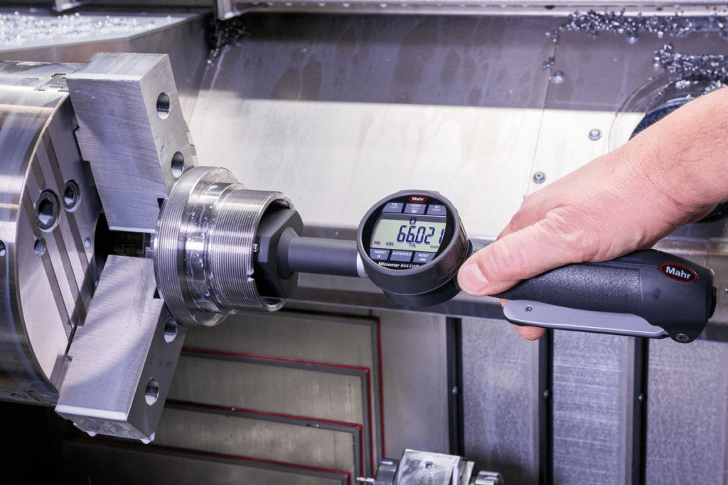
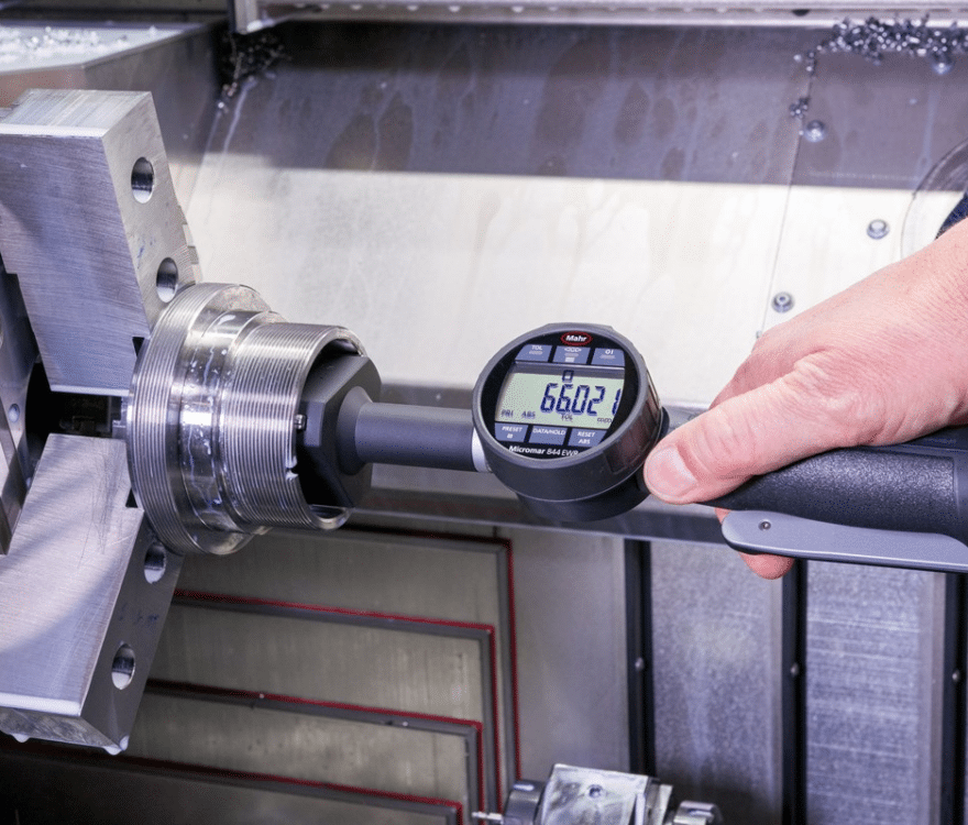
The inspection method also matters. A standard caliper is not appropriate for single-digit micron tolerances. Bore gauges, plug gauges, pin gauges, digital micrometers, or CMM may be required depending on feature size and tolerance. Agree on the gauge before production begins, not during first article inspection.
Interference Fit Design Checklist Before Requesting a Quote
- Nominal shaft and hole diameter confirmed?
- Are tolerance limits defined on both the shaft and the hole separately?
- Fit standard referenced: ISO 286, ANSI B4.1, or other?
- Are materials specified for each mating part, including heat treatment?
- Coatings, plating, or anodizing specified with a thickness range?
- Surface finish called out on mating features?
- Assembly method defined: cold press, hydraulic, shrink fit, or cryogenic?
- Assembly permanent or must it be serviceable?
- Required holding force or torque documented?
- Temperature range in service considered?
- Inspection method specified for mating features?
- Responsibility for fit verification confirmed if parts are sourced separately?
When to Discuss the Fit with Your Manufacturing Partner
Several situations call for a review before machining starts rather than after:
- The interference range is narrow, particularly below 0.020 mm across the combined tolerance band of both parts.
- Mating materials are dissimilar, especially aluminum-to-steel, with temperature variation in service.
- Parts have thin walls, nearby slots, or other features that raise distortion risk during pressing.
- A surface treatment is specified after machining with an undefined thickness tolerance.
- Assembly force is constrained by available equipment or by load limits on the assembled part.
- A prototype fit is moving to volume production, where small issues manageable at low quantity become yield problems at scale.
For critical shaft and hole fit features, confirming the tolerance strategy before machining is far less expensive than diagnosing fit problems during assembly. Zintilon reviews drawings, materials, and tolerance requirements during quoting, so issues are addressed before any material is cut.
Learn more about Zintilon’s quality assurance and CNC machining tolerances, or get a quote to start your project.
FAQ:
What is the difference between an interference fit and a clearance fit?
A clearance fit has the shaft always smaller than the hole, allowing easy assembly and relative movement. An interference fit has the shaft always larger than the hole, so dimensional overlap creates contact pressure that holds the parts together.
What is the difference between interference fit and transition fit?
A transition fit may produce small clearance or small interference depending on where actual dimensions fall within the tolerance range. An interference fit is designed so that the shaft is always larger than the hole across the full tolerance range of both features.
Is press fit the same as interference fit?
Not exactly. Interference fit is the dimensional condition; press fit is the assembly method. Most press fits involve interference, but interference fits can also be assembled by heating the outer part or cooling the inner part rather than pressing.
How much press fit tolerance is needed?
There is no universal answer. It depends on nominal diameter, material elastic properties, wall thickness, surface finish, temperature range, required holding force, and assembly method. Specify tolerance limits or a recognized fit standard rather than relying on a generic drawing note.
Can CNC machining achieve interference fit tolerances?
Yes, but the achievable tolerance depends on feature size, material, geometry, and process. Boring, reaming, and cylindrical grinding cover most interference fit requirements. Critical features may need dedicated inspection with bore gauges, plug gauges, or CMM. Define the inspection plan before production begins.
Great, Together